
Almost one in every four Americans has a tattoo,
according to a 2006 study conducted by the Journal of the American Academy of Dermatology.
However, this common procedure poses the risk of serious disease transmission to both the artist and their customers. Possible infections as a result of inadequately sterilized reusable equipment range from Staphylococcus Aureus, (including a potentially deadly, drug-resistant type of staph infection that has been reported among unlicensed tattoo artists in at least three states), to Hepatitis C and HIV.
Infection control areas in tattoo studios where reusable equipment is sterilized are often in nonvisible rooms as discussion surrounding infection control, and the equipment they use can often be seen to be as intimidating to customers.

SciCan, the world leader in tabletop autoclaves has developed a tattoo-specific machine that will not only optimize the sterility of reusable equipment, but will put infection control front and center – namely, right front of the customer.
Smaller, lighter and more portable than a traditional device, the ‘STATTOO’ is designed to be located right in the procedure area so customers can see the sterilization process and ensure they are receiving freshly sterilized instruments.
In addition, the ‘STATTOO’ can sterilize 10x faster (6 mins vs. 60 mins) than conventional devices – which is fast enough to sterilize between procedures – an industry first. This unprecedented speed greatly reduces instrument bottlenecks and provides tattoo professionals opportunity to increase the number of procedures possible due to the speed in which instruments can be introduced back into the workflow.
With an exterior design by tattoo artist Scott McEwan, ‘STATTOO is an extremely unique product offering for a community that continues to face more complex infection control challenges’ says Andrew Zwingenberger, National Sales Manager for SciCan Medical USA ‘with a look that compliments its surroundings.’
‘STATIM is designed to exceed those infection control challenges faced by the body art professional’. He continues, ‘quite frankly, this product will not only provide tattoo artists a distinct performance advantage, but we see this as an opportunity to show off their sterilization process – front and center – and generate dialogue about infection control with their customers’.
The STATIM 900 autoclave is currently not in production, but may return as a G4 version in the future.

Replacement cover for Statim 2000 G4 autoclaves
Replace it!
More details: Technical Service Bulletin 21-TSB-424
Description:
Implementation of the new G4+ LCD Controller board for STATIM® G4 2000 and 5000.
Models and Markets: All STATIM® G4 units; worldwide.
Summary:
- Replace a 3rd Generation (G4+) LCD board with a 3rd Generation (G4+) LCD board.
- Replacement 2nd Generation (Next Gen) LCD boards continue to be available. Use 2nd Generation (Next Gen) LCD boards to replace 2nd Generation (Next Gen) LCD boards.
- Replacement 1st Generation (Old Gen) LCD boards are no longer available. Replace 1st Generation board using a complete cover assembly that includes a 2nd Generation (Next Gen) LCD board.
1. Identifying LCD controller boards
Identifying whether it is a 1st Generation (Old Gen), 2nd Generation (Next Gen) or 3rd Generation (G4+) LCD controller board.
On a functioning unit
If the unit is functioning, press Settings to view the unit’s software version information.
 =>
=>
Figure 1. Press SETTINGS to find the software versio

n number.
|
SOFTWARE VER. NUMBER |
SL00R1XX |
SL01R128 and up |
SL12R100 and up |
|
LCD BOARD TYPE |
1st Generation (Old Gen) LCD Board |
2nd Generation (Next Gen) LCD Board |
3rd Generation (G4+) LCD Board |
|
WHAT TO DO |
Units with LCD controller boards with ‘SL00’ series software (SL00R1XX) will require a complete replacement cover that comes with all needed components pre– see 1st Generation LCD Board 10-112305 in the spare parts Table 3 in section 3, below. |
Units with LCD controller boards with ‘SL01’ series software (SL01R128 and up) will require only the replacement of the LCD controller board – see 2nd Generation LCD Board 10-114610 in the spare parts Table 3 in section 3, below. |
Units with LCD controller boards with ‘SL12’ series software (SL12R100 and up) will require only the replacement of the LCD controller board – see 3rd Generation LCD Board 10-116682 in the spare parts Table 3 in section 3, below. |
Table 1. Identifying board types using software versions.
On a non-functioning unit
If the unit’s LCD is not functioning, you will have to remove the cover and fascia and read the information that is printed on the LCD controller board as shown in Table 2.
|
BOARD TYPE AND NUMBER |
WHERE THE NUMBER IS LOCATED ON THE BOARD |
WHAT TO DO |
|
1st Generation (Old Gen) LCD Board 10- 112305 |
|
Units with an LCD controller board part number 10-112305 (old generation) will require complete replacement cover that comes with all needed components preassembled – see 1st Generation LCD Board 10-112305 in the spare parts table in section 3, below. |
|
2nd Generation (Next Gen) LCD Board 10- 114610 |
|
Units with an LCD controller board part number 10-114610 (next generation) will require only the replacement of the LCD controller board – see 2nd Generation LCD Board 10-114610 in the spare parts table in section 3, below. |
|
3rd Generation (G4+) LCD Board 10-116682 |
|
Units with an LCD controller board part number 10-116682 (G4+) will require only the replacement of the LCD controller board since the LCD touch screen and unit fascia are compatible with the G4+LCD controller board –see 3rd Generation LCD Board 10-116682 in the spare parts Table 3 in section 3, below. |
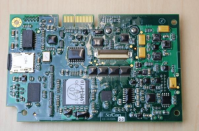
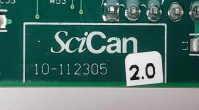

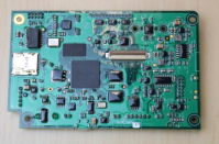
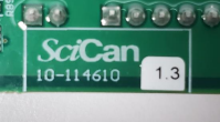

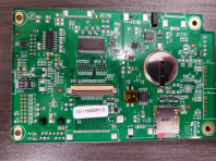
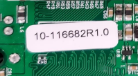

Table 2. Identifying board types visually.
2. What models are affected?
STATIM units built in or after May 2022 will have the 3rd Generation (G4+) LCD Controller boards.
3. Determining the spare parts you will need
|
1st Generation (Old Gen) LCD Board 10-112305 |
Statim 5000 WIFI |
01-114710S Cover NextGen WIFI ST5000S G4 noP |
|
Statim 5000 no WIFI |
01-112393S Cover NextGen ST5000S G4 no Printer |
|
|
Statim 2000 WIFI |
01-114706S Cover NextGen WIFI Complete 2000G4 |
|
|
Statim 2000 no WIFI |
01-112414S Cover NextGen Complete ST2000 G4 |
|
2nd Generation (Next Gen) LCD Board 10-114610 |
Statim 5000 WIFI |
01-115465S Logic WIFI PCB Statim G4 NextGen |
|
01-115318S LCD NextGen module Statim 5000/SG4 |
||
|
01-114710S Cover NextGen WIFI ST5000S G4 no Printer, for units with Rev 7 controller boards |
||
|
01-115563S Cover NextGen WIFI 5000S G4 no Printer, for units with Rev 8 controller boards |
||
|
Statim 5000 no WIFI |
01-115313S Logic PCB Statim G4 NextGen Kit |
|
|
01-115318S LCD NextGen module Statim 5000/SG4 |
||
|
01-112393S Cover NextGen ST5000S G4 no Printer, for units with Rev 7 controller boards |
||
|
01-115562S Cover NextGen 5000S G4 no Printer, for units with Rev 8 controller boards |
||
|
Statim 2000 WIFI |
01-115465S Logic WIFI PCB Statim G4 NextGen |
|
|
01-115317S NextGen LCD module Statim 2000/SG4 |
||
|
01-114706S Cover NextGen WIFI Complete 2000G4, for units with Rev 7 controller boards |
||
|
01-115565S Cover NextGenComplete WIFI 2000G4, for units with Rev 8 controller boards |
||
|
Statim 2000 no WIFI |
01-115313S Logic PCB Statim G4 NextGen |
|
|
01-115317S NextGen LCD module Statim 2000/SG4 |
||
|
01-112414S Cover NextGen Complete ST2000 G4, for units with Rev 7 controller boards |
||
|
01-115564S Cover NextGen Complete ST2000 G4, for units with Rev 8 controller boards |
|
3rd Generation (G4+) LCD Board 10-116682 |
Statim 5000 WIFI |
01-116785S Logic PCB Statim G4+ WIFI kit |
|
01-115318S LCD NextGen module Statim 5000/SG4 |
||
|
01-116779S Cover G4+ Complete WIFI 5000S NoPr, 8 |
||
|
Statim 5000 no WIFI |
01-116784S Logic PCB Statim G4+ kit |
|
|
01-115318S LCD NextGen module Statim 5000/SG4 |
||
|
01-116776S Cover G4+ Complete 5000S NoPrinter,8 |
||
|
Statim 2000 WIFI |
01-116785S Logic PCB Statim G4+ WIFI kit |
|
|
01-115317S NextGen LCD module Statim 2000/SG4 |
||
|
01-116778S Cover G4+ Complete WIFI 2000G4, 8 |
||
|
Statim 2000 no WIFI |
01-116784S Logic PCB Statim G4+ kit |
|
|
01-115317S NextGen LCD module Statim 2000/SG4 |
||
|
01-116777S Cover G4+ Complete ST2000 G4+, 8 |
Table 3. Determining the spare part kit number.
4. Replacing an LCD controller board
1st Generation (Old Gen) LCD Board 10-112305
To complete this repair, replace the cover using a complete cover replacement kit that includes a cover, fascia, LCD controller board, and LCD display module with decal. See Service Guide for instructions on removing and replacing the cover.
IMPORTANT!
- Before you begin the repair, record the original unit’s serial number, cycle count and calibration offset values.
- Remove the MicroSD card from the old LCD controller board in the cover assembly and copy the SCILOG folder to a computer.
- Remove the MicroSD card from the new LCD controller board in the new cover assembly and insert it into the microSD card reader connected to your computer.
- Select the SCILOG folder on your computer and copy it to the microSD card. If the computer prompts you to replace existing folders and /or directories, select ‘Yes to All.’
- Insert the microSD card into the new LCD controller board in the new cover assembly and install the new cover assembly.
- On completing the repair, calibrate the level.
2nd Generation (Next Gen) LCD Board 10-114610
To complete this repair, you can replace the LCD controller board only or perform a complete cover replacement using the kit that includes a cover, fascia, LCD controller board, and LCD display module with decal. See Service Guide for instructions on removing and replacing the cover and LCD controller board.
IMPORTANT!
- Before you begin the repair, record the original unit’s serial number, cycle count and calibration offset values.
- Remove the MicroSD card from the old LCD controller board and copy the SCILOG folder to a computer.
- Remove the MicroSD card from the new LCD controller board and insert it into the microSD card reader connected to your computer.
- Select the SCILOG folder on your computer and copy it to the microSD card. If the computer prompts you to replace existing folders and /or directories, select ‘Yes to All.’
- Insert the microSD card into the new LCD controller board and install the new LCD controller board.
- On completing the repair, calibrate the level.
3rd Generation (G4+) LCD Board 10-116682
- Record the original unit’s serial number, cycle count and calibration offset values.
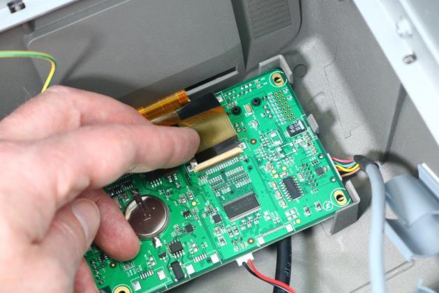
- Remove the LCD controller board.
- Remove the MicroSD card from the old LCD controller board and copy the SCILOG folder to a computer or USB device for the customer to preserve the cycle records.
- On the new LCD board, connect the Ethernet cable, RS232 communication cable to the main controller, speaker and USB. Connect the grounding wire.

- Connect the LCD display ribbon cable, pushing it down into position and closing the hinged connector. Give the ribbon cable a gentle tug to ensure it is properly held in position.
- Reinstall the cover.
- Power the unit ON. It may take a few minutes for the software to load. Once the Home screen appears, check that the unit has the correct serial number, cycle count and calibration values. If the unit does not have the correct information, go to the technician menu and activate the BACKUP NVRAM function. Check the other unit settings and adjust as needed.
- Calibrate the level.
IMPORTANT!
When the cover is removed, a dielectric strength test (Hi-Pot) AND a protective bonding impedance test (ground continuity) must be performed on the STATIM when the work is completed and after the cover has been returned to the unit.


