

We are proud to announce the launch of SciCan OPTIM OS1 Liquid to round out our new line of OPTIM OS1 broad-spectrum, hospital-grade cleaner-disinfectant products.
OPTIM OS1 is a one-step, cleaner-disinfectant that removes soil and hard-to-kill organisms from clinical contact surfaces. It’s proprietary LAS Active System formulation kills bacteria, viruses, TB bacteria, and emerging pathogens in just 1 minute.
Rapid contact times for best results
- 60-second kill times for viruses, bacteria, and yeast
- Kills TB Bacteria in only 45 seconds and Candida auris in 60 seconds
Safe for use on hard, non-porous clinical surfaces
- Cleans and disinfects stainless steel, anodized aluminum, non-porous upholstery, Corian countertops, silicone, and more
Formulated with the user in mind
- VOC-free, fragrance-free and dye-free
Emerging Pathogen Claim ensures your clinic is ready for the next viral
threat
- Qualifies for EPA’s Emerging Viral Pathogen Claim
- Kills SARS-CoV-2, the virus that causes COVID-19, in only 30 seconds
You can learn more about OPTIM’s newest formula below

OPTIM OS1 Wipes Quick Reference Guide
Consult the product label before using this surface disinfectant.
OPTIM OS1 SOLUTION Liquid Spray

Spray Ready-to-Use OPTIM OS1 liquid onto a SciCan Dry Towelette. Do not directly spray onto the surface.

If surface is not heavily soiled, clean and disinfect surface with one wipe and allow surface to remain wet for the contact time indicated on the label.

If surface is visibly soiled, clean surface with one
towelette and discard. Use a second towelette to disinfect and allow surface to remain wet for the contact time indicated on the label.
OPTIM OS1 Ready-to-Use Wipes

Pull out OPTIM OS1 towelette at a 45 degree angle. Close lid.
If surface is not heavily soiled, clean and disinfect surface with one wipe and allow surface to remain wet for the contact time indicated on the label.
If surface is visibly soiled, clean surface with one towelette and discard. Use a second towelette to disinfect and allow surface to remain wet for the contact time indicated on the label.
IMPORTANT !
DO NOT allow OPTIM OS1 to pool on surfaces.
Use of gauze dipped in solutions for wiping may cause pooling and should be wiped dry.
FOR BEST RESULTS:
- Do not over apply OPTIM OS1
- Use of OPTIM OS1 on brass, copper, and clear acrylic could discolor or damage surfaces, if not used as directed and over applied.
- Dental Association guidelines recommend the use of utility gloves when cleaning and disinfecting surfaces.
PLEASE REFER TO THE ORIGINAL CONTAINER FOR COMPLETE DIRECTIONS AND ADDITIONAL INFORMATION.
Procedure for disinfecting PVS elastomeric impression materials with OPTIM OS1
- Once the impression is taken, rinse it well under running tap water to remove blood and saliva.
- After rinsing, gently shake the impression within the sink basin to remove any adherent water with minimal splatter.
- Spray the entire impression with OPTIM OS1. Use the contact times as stated on the label.
- Rinse the impression thoroughly with tap water to remove any excess disinfectant. After a thorough rinse, gently
shake the impression inside the sink basin to remove any adherent water with minimal splatter. - Once dry, place the disinfected impression in a sealed bag.
The impression is now safe and ready for further processing.

Switching to OPTIM OS1
- Give all surfaces a good cleaning with soap and water before switching to OPTIM OS1.
- After switching to OPTIM OS1, surfaces should to be periodically rinsed with water (recommended no less than once per week).
- Common practice for all chemical disinfectants is to periodically rinse and dry surfaces to maintain the surface integrity.
- Avoid mixing of chemistries.


Replacement cover for Statim 5000 G4 autoclaves
Replace it!
More details: Technical Service Bulletin 21-TSB-424
Description:
Implementation of the new G4+ LCD Controller board for STATIM® G4 2000 and 5000.
Models and Markets: All STATIM® G4 units; worldwide.
Summary:
- Replace a 3rd Generation (G4+) LCD board with a 3rd Generation (G4+) LCD board.
- Replacement 2nd Generation (Next Gen) LCD boards continue to be available. Use 2nd Generation (Next Gen) LCD boards to replace 2nd Generation (Next Gen) LCD boards.
- Replacement 1st Generation (Old Gen) LCD boards are no longer available. Replace 1st Generation board using a complete cover assembly that includes a 2nd Generation (Next Gen) LCD board.
1. Identifying LCD controller boards
Identifying whether it is a 1st Generation (Old Gen), 2nd Generation (Next Gen) or 3rd Generation (G4+) LCD controller board.
On a functioning unit
If the unit is functioning, press Settings to view the unit’s software version information.
 =>
=>
Figure 1. Press SETTINGS to find the software versio

n number.
|
SOFTWARE VER. NUMBER |
SL00R1XX |
SL01R128 and up |
SL12R100 and up |
|
LCD BOARD TYPE |
1st Generation (Old Gen) LCD Board |
2nd Generation (Next Gen) LCD Board |
3rd Generation (G4+) LCD Board |
|
WHAT TO DO |
Units with LCD controller boards with ‘SL00’ series software (SL00R1XX) will require a complete replacement cover that comes with all needed components pre– see 1st Generation LCD Board 10-112305 in the spare parts Table 3 in section 3, below. |
Units with LCD controller boards with ‘SL01’ series software (SL01R128 and up) will require only the replacement of the LCD controller board – see 2nd Generation LCD Board 10-114610 in the spare parts Table 3 in section 3, below. |
Units with LCD controller boards with ‘SL12’ series software (SL12R100 and up) will require only the replacement of the LCD controller board – see 3rd Generation LCD Board 10-116682 in the spare parts Table 3 in section 3, below. |
Table 1. Identifying board types using software versions.
On a non-functioning unit
If the unit’s LCD is not functioning, you will have to remove the cover and fascia and read the information that is printed on the LCD controller board as shown in Table 2.
|
BOARD TYPE AND NUMBER |
WHERE THE NUMBER IS LOCATED ON THE BOARD |
WHAT TO DO |
|
1st Generation (Old Gen) LCD Board 10- 112305 |
|
Units with an LCD controller board part number 10-112305 (old generation) will require complete replacement cover that comes with all needed components preassembled – see 1st Generation LCD Board 10-112305 in the spare parts table in section 3, below. |
|
2nd Generation (Next Gen) LCD Board 10- 114610 |
|
Units with an LCD controller board part number 10-114610 (next generation) will require only the replacement of the LCD controller board – see 2nd Generation LCD Board 10-114610 in the spare parts table in section 3, below. |
|
3rd Generation (G4+) LCD Board 10-116682 |
|
Units with an LCD controller board part number 10-116682 (G4+) will require only the replacement of the LCD controller board since the LCD touch screen and unit fascia are compatible with the G4+LCD controller board –see 3rd Generation LCD Board 10-116682 in the spare parts Table 3 in section 3, below. |
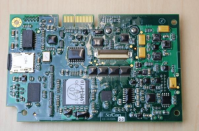
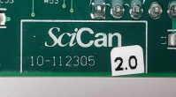

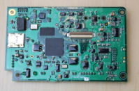
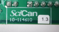

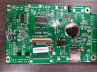
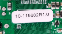

Table 2. Identifying board types visually.
2. What models are affected?
STATIM units built in or after May 2022 will have the 3rd Generation (G4+) LCD Controller boards.
3. Determining the spare parts you will need
|
1st Generation (Old Gen) LCD Board 10-112305 |
Statim 5000 WIFI |
01-114710S Cover NextGen WIFI ST5000S G4 noP |
|
Statim 5000 no WIFI |
01-112393S Cover NextGen ST5000S G4 no Printer |
|
|
Statim 2000 WIFI |
01-114706S Cover NextGen WIFI Complete 2000G4 |
|
|
Statim 2000 no WIFI |
01-112414S Cover NextGen Complete ST2000 G4 |
|
2nd Generation (Next Gen) LCD Board 10-114610 |
Statim 5000 WIFI |
01-115465S Logic WIFI PCB Statim G4 NextGen |
|
01-115318S LCD NextGen module Statim 5000/SG4 |
||
|
01-114710S Cover NextGen WIFI ST5000S G4 no Printer, for units with Rev 7 controller boards |
||
|
01-115563S Cover NextGen WIFI 5000S G4 no Printer, for units with Rev 8 controller boards |
||
|
Statim 5000 no WIFI |
01-115313S Logic PCB Statim G4 NextGen Kit |
|
|
01-115318S LCD NextGen module Statim 5000/SG4 |
||
|
01-112393S Cover NextGen ST5000S G4 no Printer, for units with Rev 7 controller boards |
||
|
01-115562S Cover NextGen 5000S G4 no Printer, for units with Rev 8 controller boards |
||
|
Statim 2000 WIFI |
01-115465S Logic WIFI PCB Statim G4 NextGen |
|
|
01-115317S NextGen LCD module Statim 2000/SG4 |
||
|
01-114706S Cover NextGen WIFI Complete 2000G4, for units with Rev 7 controller boards |
||
|
01-115565S Cover NextGenComplete WIFI 2000G4, for units with Rev 8 controller boards |
||
|
Statim 2000 no WIFI |
01-115313S Logic PCB Statim G4 NextGen |
|
|
01-115317S NextGen LCD module Statim 2000/SG4 |
||
|
01-112414S Cover NextGen Complete ST2000 G4, for units with Rev 7 controller boards |
||
|
01-115564S Cover NextGen Complete ST2000 G4, for units with Rev 8 controller boards |
|
3rd Generation (G4+) LCD Board 10-116682 |
Statim 5000 WIFI |
01-116785S Logic PCB Statim G4+ WIFI kit |
|
01-115318S LCD NextGen module Statim 5000/SG4 |
||
|
01-116779S Cover G4+ Complete WIFI 5000S NoPr, 8 |
||
|
Statim 5000 no WIFI |
01-116784S Logic PCB Statim G4+ kit |
|
|
01-115318S LCD NextGen module Statim 5000/SG4 |
||
|
01-116776S Cover G4+ Complete 5000S NoPrinter,8 |
||
|
Statim 2000 WIFI |
01-116785S Logic PCB Statim G4+ WIFI kit |
|
|
01-115317S NextGen LCD module Statim 2000/SG4 |
||
|
01-116778S Cover G4+ Complete WIFI 2000G4, 8 |
||
|
Statim 2000 no WIFI |
01-116784S Logic PCB Statim G4+ kit |
|
|
01-115317S NextGen LCD module Statim 2000/SG4 |
||
|
01-116777S Cover G4+ Complete ST2000 G4+, 8 |
Table 3. Determining the spare part kit number.
4. Replacing an LCD controller board
1st Generation (Old Gen) LCD Board 10-112305
To complete this repair, replace the cover using a complete cover replacement kit that includes a cover, fascia, LCD controller board, and LCD display module with decal. See Service Guide for instructions on removing and replacing the cover.
IMPORTANT!
- Before you begin the repair, record the original unit’s serial number, cycle count and calibration offset values.
- Remove the MicroSD card from the old LCD controller board in the cover assembly and copy the SCILOG folder to a computer.
- Remove the MicroSD card from the new LCD controller board in the new cover assembly and insert it into the microSD card reader connected to your computer.
- Select the SCILOG folder on your computer and copy it to the microSD card. If the computer prompts you to replace existing folders and /or directories, select ‘Yes to All.’
- Insert the microSD card into the new LCD controller board in the new cover assembly and install the new cover assembly.
- On completing the repair, calibrate the level.
2nd Generation (Next Gen) LCD Board 10-114610
To complete this repair, you can replace the LCD controller board only or perform a complete cover replacement using the kit that includes a cover, fascia, LCD controller board, and LCD display module with decal. See Service Guide for instructions on removing and replacing the cover and LCD controller board.
IMPORTANT!
- Before you begin the repair, record the original unit’s serial number, cycle count and calibration offset values.
- Remove the MicroSD card from the old LCD controller board and copy the SCILOG folder to a computer.
- Remove the MicroSD card from the new LCD controller board and insert it into the microSD card reader connected to your computer.
- Select the SCILOG folder on your computer and copy it to the microSD card. If the computer prompts you to replace existing folders and /or directories, select ‘Yes to All.’
- Insert the microSD card into the new LCD controller board and install the new LCD controller board.
- On completing the repair, calibrate the level.
3rd Generation (G4+) LCD Board 10-116682
- Record the original unit’s serial number, cycle count and calibration offset values.
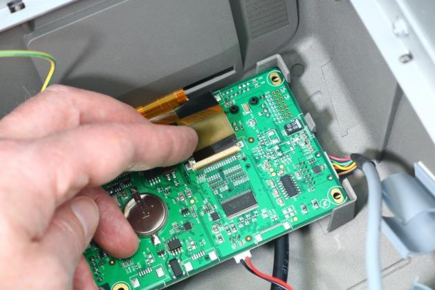
- Remove the LCD controller board.
- Remove the MicroSD card from the old LCD controller board and copy the SCILOG folder to a computer or USB device for the customer to preserve the cycle records.
- On the new LCD board, connect the Ethernet cable, RS232 communication cable to the main controller, speaker and USB. Connect the grounding wire.

- Connect the LCD display ribbon cable, pushing it down into position and closing the hinged connector. Give the ribbon cable a gentle tug to ensure it is properly held in position.
- Reinstall the cover.
- Power the unit ON. It may take a few minutes for the software to load. Once the Home screen appears, check that the unit has the correct serial number, cycle count and calibration values. If the unit does not have the correct information, go to the technician menu and activate the BACKUP NVRAM function. Check the other unit settings and adjust as needed.
- Calibrate the level.
IMPORTANT!
When the cover is removed, a dielectric strength test (Hi-Pot) AND a protective bonding impedance test (ground continuity) must be performed on the STATIM when the work is completed and after the cover has been returned to the unit.


